Arduino Smartwatch With Custom PCB
- Jan 11, 2021
- 6 min read
Hi all, in this article you will see how a smartwatch can be made using an Arduino board and a few other components. We are going to design and get a custom PCB fabricated which will be the motherboard of our watch housing the main circuit and the brain of the watch ATmega 328P which we will salvage from an Arduino Nano board.
I have chosen the Arduino Nano and not the more commonly used Arduino UNO because the Nano features a Surface Mount chip so it's much more compact and in this project, space is key because we need to fit all the components in the least space possible.
I am going to use a 160 mAh Li-Po (Lithium Polymer) battery which will easily be able to power the watch on regular use for at least a week which is quite good enough. We will use a USB battery charging module for charging the battery. This will also have a USB port in it to charge the battery!
I have designed the body of the watch in a 3d design software and you can easily get it 3d-printed anywhere. This was we can keep the watch completely personalised according to your need. The watch will be activated by using a push-button present at the side of the watch.
The watch will have Bluetooth functionality and will be connected to an app that can be used to track data. It can count the steps, distance and the calories burnt using an accelerometer module. With the same components and in some iterations in the code and the app, we can also easily track messages and calls received on the phone through the smartwatch! The watch will also have a heart rate measuring sensor in it which will be able to measure your pulse and I have tried it out. It's pretty accurate!
This was a little info about the project that we are going to work on. So let's begin.
Step 1: Gather the Components

Components:
Arduino Nano
DS1302 Real Time Clock Module (Only the DS1302 chip needed)
TP4056 Battery Charging Module
ADXL335 Accelerometer Module
100K Value SMD Resistor
10K Value SMD Resistor
Pulse Sensor
USB to TTL Interface (For programming the ATmega 328P)
0.96 inch OLED Display
HM-10 Bluetooth Module
Tools:
Soldering Iron
Hot Air Soldering Station (for self-assembly)
A Set of Precision Tweezer Set (optional - makes picking components easy)
3D Printer (optional - can get it third-party 3D printed)
Precise Soldering Wire
I always prefer Quartz Components for buying electronic components in India!
Step 2: Why Custom PCB?
We can clearly see here that if we were to use the components as it is then it would look like you are carrying a big box on your wrist and I definitely don't think that is a great idea! Also, it would be tedious work connecting the modules together inside that little area.
Thus building a custom PCB is the best option we got at this point in time. We can eliminate the use of any wires and also can eliminate all the unnecessary components of these modules and salvage the components that we need from these boards and put all of them on one single board.
I will attach the schematic diagram in this instructable and also the Gerber files of the PCB so you can even modify the PCB design based on your needs.
Step 3: Schematic and PCB design

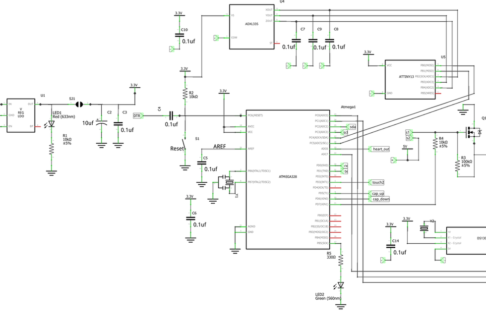
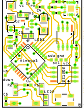
I have designed the schematic in a way that we utilise only the required components from all the modules and eliminated all the redundant or unnecessary components from the modules. I have attached the schematic diagram of the PCB in the instructable so you can have a look and change it according to your needs. I have also attached the PCB designs that I made here so you can modify them as well!
The schematic has the schematic of the Arduino board embedded in it so what we need to do is just salvage all the components of the Arduino Nano board and just resolder them here. You can also get your PCB assembled by various companies as many PCB fabricating companies even offer assembly services!
PCB Gerber - Link to the Gerber files of the PCB which you can import into any PCB design software and edit them according to your needs.
Step 4: Stacking the Components

The components that will finally go in our smartwatch body are:
OLED Display
Custom PCB
Bluetooth Module
Battery Charging Module
Heart Rate Sensor
Small Push Button
It is important to note here that you must not expect our watch to be sleek like an apple watch! It will be quite big in size because we are not designing an industry-grade smartwatch because industry-grade smartwatches would never use an Arduino board. They have microprocessors that have Bluetooth, fitness tracking inbuilt in them eliminating most of the other modules! This smartwatch is just a prototype and it is a simple demonstration of the capabilities of the Arduino board and if you want to show off your geek creations you can indeed wear the watch to school 😛. Next, we move on to the body of the watch where all these components will be housed!
Step 5: Body of the Smartwatch


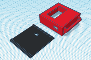
Now we have to design the body of the smartwatch. I have made a very easy design in Tinkercad and you can obviously get your hands dirty and make your own design for the body of the smartwatch! I wanted to give it a different look so I did not even curve the edges and am making it in a simple cuboidal shape. I have attached my designs for you to check out. You can even use the same designs. I will add the design files in the description below.
There are four cutouts in the design for:
The Display
The Push Button to power the watch
The Pulse Sensor
Charging USB port
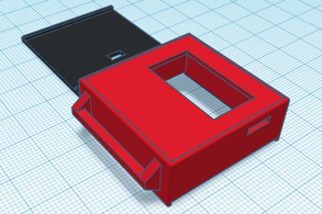
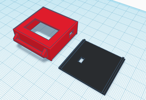
There are also two small protrusions on the side of the watch for the straps. You can use any straps on the watch that have a similar mechanism. The watch body has two pieces. It has a top piece which has 5 sides and a bottom plate which I have designed in a way that it can snap-fit to the top piece very easily and there is no need of glueing or taping anything so it looks cleaner.
In the images I have attached below, you can see two parts. The red piece is the top piece and the black piece is the bottom one.
Step 6: Workflow of the Watch

We obviously cannot keep the watch powered all the time because we need to preserve the battery at all costs. So for that what we will do is we will use a self-kill method in which we will programmatically tell the Arduino to get disconnected from the power source. So when the user presses the power button it will automatically go off after a designated time, say 5 seconds. This way we can get the watch to function seamlessly!
You might think that if the watch keeps killing the power continuously then how will the Arduino board retain the step-tracking data! For that, I have a great solution to offer. What we will do here is that we will be using an ATtiny85 chip that uses very little power and we will keep that powered forever while barely consuming any battery! We will also connect the accelerometer module to the ATtiny chip so it keeps tracking the steps forever and whenever the Arduino board is powered it will ask the ATtiny board for all of the data. This is a great technique to keep only a part of the watch functioning all the time instead of the whole watch itself!
Using the accelerometer module we will track steps and using these we will calculate the distance travelled. Using all this data we can easily programmatically calculate the calories burnt by the person and when we connect the watch to the smartphone using Bluetooth we can use an app to view all the data or also view the data in the watch itself.
Step 6: The Code for the Smartwatch
Now we come to the most important part of the process and that's coding the smartwatch. This won't be tough in our scenario because it is just a static device and there is no mechanics involved which already makes the Arduino coding 90% easy!
For now, I have not completely written the code of the smartwatch so I insist you try out the code yourself and if the algorithms and the code work out then I'll surely feature your entries in the instructable. This will make the entire process more interactive and that is how it should be.
I will surely include a version of my code in future iterations so stay tuned! Good Luck!


Comments